Simple tweak for breadboard power modules
Nowadays breadboards are often sold with a breadboard power module and a bunch of jumper wires included. This power module allows you to easily apply 5 and/or 3.3 volt to the power rails of the breadboard using an external power source. However, often you need a higher voltage in your project as well, maybe 9 or 12V to power your Arduino, relay, audio amp, etc. This little tweak shows you a simple yet effective solution.
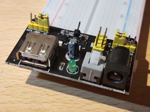
A breadboard power module is a simple way to apply DC voltage to a breadboard. Most modules do have two inputs: USB and a DC barrel connector. The DC input runs a 5V regulator, and the output of this regulator is fed to a 3.3V regulator. Jumpers allow you to select which voltage is applied to which power rail of the breadboard. The module also often includes a switch to turn the power on/off, a LED indicating the power state, a diode to rectify the input voltage when using an AC source (not recommended) and a capacitor to flatten the DC voltage.
I play a lot with microcontrollers, especially Arduino. In most cases I combine the microcontroller with all kinds of electronics and modules, and connect everything using a breadboard. The breadboard is not only useful to build electronic circuits, but can also be used as a patch board for power and signals.
The best/safest way to power the Arduino is by using an external power source with a barrel connector or the ‘Vin’ pin. Arduino recommends 7 Volts or more. However, when using a breadboard power module, you only have 3.3V and 5V available.
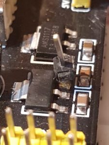
The simple solution is to solder an extra pin on the power module that provides you the required voltage. The best place is probably on the input pin of the 5V regulator, so that the pin’s voltage is also turned off when pressing the power switch.
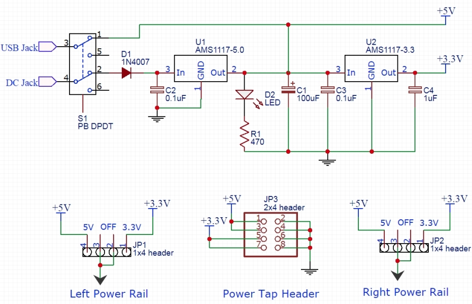
The picture just above shows an example of a breadboard power module circuit. The DC-input passes a switch (S1) and a diode (D1) before entering the 5V regulator (U1). By soldering a jumper pin on the input of the 5V regulator (pin 3 of U1, in this example), the original input voltage now becomes easily accessible. Note that in this example the voltage is 0.6V less due to the protection diode, but in most cases this won’t be a problem.
Why you should not use USB
Take a look again at the circuit. The 5V rail of your breadboard is directly connected to the 5V pin of the USB-connector. So whenever you apply a higher voltage on your breadboard’s power rail while the USB is connected to your PC or laptop, the voltage will go into your computer, which might cause serious damage! My advise: never power the module using USB from your computer, stick to an external power source (e.g. DC adapter) and connect it to the DC input of the breadboard power module. Also, the tweak described above does not work when powering over USB.
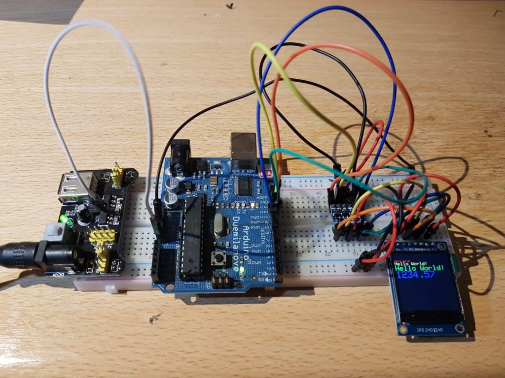
The 3.3V display is powered from the 3.3V power rail at the bottom row of the breadboard. The level converter (top left of the display) is powered by both the 5V rail on top and the 3.3V rail, and converts the voltages between the Arduino (5V) and the display (3.3V).
Hello Ernest,
Remember me from Capgemini (2006-2007)?
How are you doing? Nice to see your work here.