Squalo antenna for 6m
Introduction
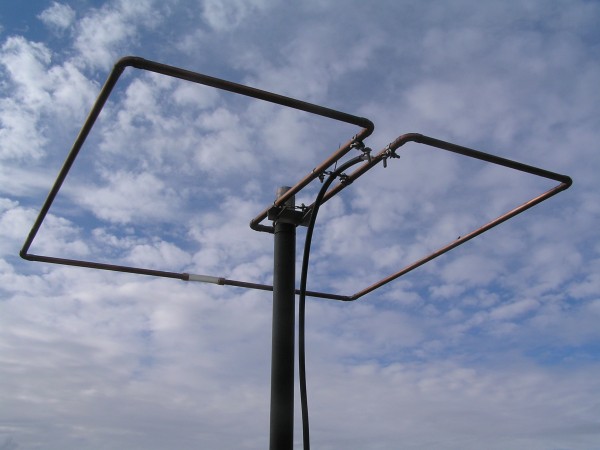
Adri PA0RDA, a friend of me, is trying to do some DX on 6m for a while now. His antenna position is very poor: he lives in the bottom flat of a 5-floor building. He has a balcony on the rear (south) side, but high buildings are very close, he has no direct sight in any direction. At the balcony he has a Diamond V2000 vertical antenna for 6/2/70, and an MFJ loop antenna for 15-40m. The 6m band is his most popular one, since he get best results on this band. However, since most DX on 6m is horizontally polarized, he needed a horizontal antenna. I remembered an all-direction horizontal antenna made by Jan PA3EGH (one of the members of the local radio club). So I contacted him, and he pointed me at his website. It was the “Squalo” antenna, or square halo. In fact, it’s just a square folded dipole, originally designed by John KG4OSA. It radiates in all directions, with -4dB gain on the sides (compared to the front and back side).
Construction
This is a copy of the design, originally published by Jan PA3EGH:
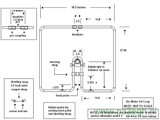
All measurements in the original design are given in inches, so let’s convert them to mm first:
| Inch | mm |
| 30,5 | 775 |
| 2,5 | 64 |
| 14,0 | 356 |
| 27,56 | 700 |
| 5,512 | 140 |
| 1,575 | 40 |
I used 12mm copper pipe for the “loop”, stainless steel strip for the shorting strap and feed point, and a small piece of PVC tube for the insulator.
The antenna is very easy to build. The website with the original design provides enough information on how to build it. The pictures suggest some construction details:
![[image]](https://www.pa3hcm.nl/wp-content/uploads/2014/01/squalo-6m-2.jpg)
![[image]](https://www.pa3hcm.nl/wp-content/uploads/2014/01/squalo-6m-3.jpg)
![[image]](https://www.pa3hcm.nl/wp-content/uploads/2014/01/squalo-6m-4.jpg)
Testing
I don’t have any equipment for 6m, except a small handy (Kenwood TH-F7) which is capable to receive 6m USB. So after building the antenna, I first attached that radio to the squalo to see if it’s doing something. And yes, it worked! There was an Italian 6m contest, and I heard lots of stations. Next I hooked up the squalo to my MiniVNA to did some tuning. I tuned it (by moving the shortening strip and feed point) to let it resonate on 50.500 MHz, and adjusted the feed point to get 50 ohms on that frequency. The antenna has an operating bandwidth of about 1 MHz, so it covers at least 50 – 51 MHz. That part of the band includes the CW and SSB areas, aswell as the beacons.
I experimented with turning the antenna around while receiving a steady signal (a beacon). There is no “dip” (like dipoles have), but when receiving at one of the sides the signals are somewhat weaker. I didn’t notice any front/back ratio.
![[image]](https://www.pa3hcm.nl/wp-content/uploads/2014/01/squalo-6m-5.jpg)
![[image]](https://www.pa3hcm.nl/wp-content/uploads/2014/01/squalo-6m-6.jpg)
Results
On August 15th 2009 I went to Adri to help him with the antennas. He’s blind, so he needs a helping hand now and then. This time we moved his “north” antenna from the living room to the roof. Also, this was a good moment to put the squalo in place, on the south side of his home. I did some final tuning (using my MiniVNA and laptop). Unfortunately the band was closed at that moment. But the day after I received an email that he worked EA5, which is over 1500 km from his site. So the antenna seems to be working.
![[image]](https://www.pa3hcm.nl/wp-content/uploads/2014/01/squalo-6m-7.jpg)
![[image]](https://www.pa3hcm.nl/wp-content/uploads/2014/01/squalo-6m-8.jpg)
![[image]](https://www.pa3hcm.nl/wp-content/uploads/2014/01/squalo-6m-ve3bxp.jpg)
![[image]](https://www.pa3hcm.nl/wp-content/uploads/2014/01/squalo-6m-pa2jsz.jpg)
![[image]](https://www.pa3hcm.nl/wp-content/uploads/2011/04/squalo-6m-ew8au.jpg)
Chris KC2JB made this great video, showing his way of building the squalo:
PA0RDA’s hamradio shack
Since I built this antenna for Adrian PA0RDA, I added some pictures of his shack here:
![[image]](https://www.pa3hcm.nl/wp-content/uploads/2014/01/squalo-6m-9.jpg)
![[image]](https://www.pa3hcm.nl/wp-content/uploads/2014/01/squalo-6m-10.jpg)
![[image]](https://www.pa3hcm.nl/wp-content/uploads/2014/01/squalo-6m-11.jpg)
This article was also published in:
Hello friend, I want to build one of these for our radio club but only have a swr meter and an ohm meter can I fully adjust and tune this with these meters?
Thank You
joe
The SWR meter tells you something about the impedance of the antenna, it tells nothing about the resonance frequency. Using a VNA or antenna analyser is therefore recommended. When not available the SWR meter will help you to get a working antenna, but the result might not be optimal.
Sir, I enjoyed making this antenna. I am wondering if I need some sort of choke on the feedline or balun. It tuned on 50.200 1.5:2 but I notice swr jumps around while tx. I tx at 100w. Thanks, AI5CA/Bob.
The combination of the position of the shortening strap,combined with the distance between that strap and the feed point should allow you to tune it to a lower SWR. I’ve never used a balun, but it’s an old discussion that pops up now and then again 😉 Without balun it works for most people, but if you’re a purist you may apply a 1-on-1 balun.
Could you please post the beam pattern?
Mic, I don’t have accurate measurements, but I know that it’s an oval shaped pattern, where the gain to the sides is about 3dB less than to the front and back.
Thank you for your reply, one last question, the only measurement I do not see is the distance that goes from the the side with the 2–14 inch sides….how long is the pipe that goes back to the around the mast, it shows the 5 1/2 inches to the shorting strap but what is the rest of the measurement? Thank you ever so much again I relly appreciate your help please respond to kd4ysh@yahoo.com thanks friend.
73’s
Joe, this is not a part of the antenna itself, it’s just a way to allow mounting the antenna to a pole. So make it long enough to have the pole in the center of the antenna, so that it balances (weight) at the pole mount.
Hello Ernest, thank you for answering my questions I have a couple more, I have 3 motorola fm 6 meter radios not side band but fm, should I build the square halo antenna or a verticle polarized? Are the 6 meter repeaters in my state usually fm or side band, I really like the horizontal antenna for the least wind resistance the slimjim 6 meter antenna is like 14 feet long. Thank you ever so much for your guidance thanks.
73’s
KD4YSH@yahoo.com
I am located in Tennessee
Joe, I live in the Netherlands so I’m not familiar with the VHF repeaters in the US. FM repeaters are usually vertical polarized, so the slim jim will be your choice for this. Horizontal polarization is commonly used for SSB and CW communications, so the squalo will be very suitable for this.
What is the power rating of this antenna ?
Steve, the copper itself should easily handle 1 kW RF (probably much more). Pay special attention to the connection of the coax to the copper, and the contact between the shortening strip and the copper. For high power applications I would probably drill the copper pipe and fix those connections with self-tapping screws and tand lock washers to ensure good contact.
73, Ernest PA3HCM
I’m interested by your antenna but, I think there is some problems with your inch-mm conversion.
In the table I see that 30,5 inches equals 64 mm and 27,56 inches equals 700mm.
Normally 1 inch = 25,4 mm
I think there is a mixture in the table.
Fabian, you’re absolutely right. It’s probably some copy & paste failure. I’ve updated the table, 30.5 inches equals 775 mm. Thank you for the correction.
Hi. Imthinking about building the antenna, but only have 16mm aluminium, so when it’s says center to centre, would there be ay adjustment when using 16mm instead of 12mm.
Yes, I would suggest to remain the outer dimensions.
Hello Ernest. I finally found what I have been looking for !!! We live in a senior citizens mobile home park with very restrictive rules on antennas . I have a all band HF verticle that I convinced them in thinking it is for emergency use so I was allowed to have it . I needed an antenna that looks like a tv antenna which they will allow and the squalo will work . Question ,are the side dimentions and front & back of the pipe inside or outside ?Thank you for the construction and use of the antenna .
73 Jim .
Jim, nice to hear that this antenna has enough “stealth” capabilities for your purpose 😉 The original design mentions 1/2 inch tubing. However the diameter is not critical, so choose a diameter that is strong enough to stay in shape. I used 12mm copper tubes, which is rather heavy but very solid. You can also bend a piece of sturdy metal wire in the correct shape. All given dimensions are center to center, unless otherwise noted. Sizes are not very critical, since you can easily adjust the resonance frequency by moving the shortning strap.
I built the antenna to the specs published and unless I have made a huge error reading the drawing something is bad wrong. I have a RigExpert RG-54 antenna analyzer and all my parameters are terrible. Using the drawing the initial settings these these are my readings: swr 6.1, R = 7.7ohms, IZI = 11.4 ohms, X= 8.7 ohms, L =28nH. I’m using a 6′ lead of RG213 for the connection.
Any ideas on where to look for problems?
I hope you didn’t forget the shortening strap?
I was looking up the 6m squalo and ran across your page. I just finish building one of these antennas using the same plans. By just finished, I mean I just put the last bolt in the mast support about an hour ago. I will attach the feed line tomorrow and start tuning it.
Do you know if this antenna needs an RF choke by wrapping the feed line? I was thinking that it might in order to reduce the common mode current on the outside of the coax braid. Feeding a balanced antenna with an unbalanced feed line is bound to have common mode problems.
Is this something you have tested or tried? Also, I was wondering how long of a feed line tail to attach to it? I will be using a barrel connector to attach the rest of the coax to run to my rig. I was just wondering if there was a suggestion on how long to make the piece attached to the antenna?
Shawn,
Formally a 1:1 balun should be used, since this is a symmetric antenna (balanced) feeded with coax (unbalanced). However, I’ve never experienced any issues without the balun.
You should tune the antenna so that its impedance is 50 ohms. The result is that the length of the feeder doesn’t matter anymore, since the whole system is 50 ohms. If you plan to use a balun, first tune the antenna to 50 ohms with coax directly attached (without balun). When the resonance frequency antenna is correct and the impedance is 50 ohms, insert the balun and verify that the antenna system is still 50 ohms.
If you have some pictures of your antenna, please send me an email with the pictures attached and I will add them to this article to inspire future builders and share the knowledge.
I would be interested in any information on a stacking harness.
Unfortunately I don’t have any numbers considering stacking squalo antennas. However, the squalo is quite simular to the K0FF loop and people have been stacking these loops. I found this discussion that may help you: http://www.eham.net/ehamforum/smf/index.php?topic=26519
I built an almost identical 50 MHz square loop about 8 years ago and mounted it on my pickup that I used for pulling my camper. It exhibited a very low SWR over the bottom half of 50 Mhz. I used it with my FT-857d and it consistently out performed my 1/4 wave steel whip that I also had on the truck. Unfortunately, I lost my original drawing with the measurements and the antenna itself was destroyed by a very low tree limb while off road 4×4 in a mountain forest (heading for a high point on that mountain!). The only difference was that I used a shorter distance from the shorting bar to the support mast in order to put the antenna more forward over the pickup bed from the bumper and then added a support from the mast to the pvc spacer. Now you have me wanting to build another square halo for a summer project!
Dear Friend.
newly start the construction of the antenna scualo six meters, I have two queries.
1. The antenna has front or back side is the same
2. The assembly on the mast is isolated or not
atto remain your comments.
Oscar. CE5CSV
South Los Angeles CHILE
Oscsar,
1) The antenna has about the same gain in both front and rear direction, about -3dB on the sides.
2) No isolation is needed. The shortening strap is part of the radiating system, the part between strap and mast has only a mechanical purpose, not an electrical. I suggest you do not isolate the antenna for lightning protection (assuming your mast/pole is grounded properly).
73, Ernest PA3HCM
to start cutting the pieces measures the parts where this short strap missing.
Atte
Oscar CE5CSV
South Los Angeles CHILE
Sorry Oscar, maybe I don’t understand your question, but I wouldn’t cut the pipe at the position of the shorting strap.
Dear friend Ernest.
Thank you for your answer, just missing the 2 pieces measures where this strap short, these measures are not lacking tubes ok.
Thank you
Oscar
Ok, now I understand you. That size is not critical. The drawing says: “adjust length to balance on mast”, so I would suggest about 15 inches (38 cm, just a bit more than the length of the sides).
Ernest friend Thanks for your answers, please check the plane of the antenna missing two measures. 73 good luck.
Hi OM Ernest,
the measurements given are center to center or outside tubing ?
Best Regards
Hi Arno,
Aall measurements are center to center. I’ve updated the text, since you’re not the first asking this.
73, Ernest PA3HCM
Hi guys.
I have built a Squalo for 2m. I am using it in a vertical plane. Defensively not my 7/8 wave vertical but still had nice comms with repeaters some 100km away running 50W and antenna at 6m.
Then an brain flash hit me : why not a yagi style beam consisting of Squalo elements? After all the Squalo basically could be seen as a “half size” quad loop… Hi hi.
Are there someone who have tried it… Just trying not to spend many a nights number crunching to model and try to built it just to realise a standard quad beam works way better.
Johann ZS6L
WHATSAPP +27 01 305 4108
Hi Johann, thanks for the inspiring idea! I think you end up with a moxon beam 😉
73, Ernest PA3HCM
This antenna is for listening 360. So then you can get on a beam or what ever.
Salute!
Ernest, thank you for sharing your knowledge of the Squalo antenna for 6 meters. I have built one to your specifications and have made a number of local contacts with it while lying on my workbench inside my house. However, it needs to go outside and onto a mast as my wife doesn’t appreciate exotic copper sculpture art in the house for some silly reason.
So my question is about mounting. I want to mount my squalo directly to a fiberglass mast. It appears in any photo I’ve seen of other’s work, the mast is a conductive material (steel or aluminum) and attached directly to the squalo. I perceive that as making the mast part of the antenna but, is it? TIA WA2SEA
Thomas, the mast’s material doesn’t matter. Everything behind the shortening clamp is not part (electrically) of the antenna.
btw… art needs public, so get your squalo outside ASAP 🙂
Hello Ernest, I built my own squalo following the measurements on your website and it immediately works without additional tuning. 73s Christian, DG7FEQ
Hi Ernest. One day on the Squalo:
https://flic.kr/p/KG7wMx
Best regards Wald SP3UR
Good day,
What would be the max rf power for the antenna?
Cheers!
Janusz ve2zhp
I don’t have any power ratings, it depends on the construction. My construction would easily allow a few hundred watts.
I see you wonder about power rateings. Run LMR 400 FLEX TO IT run 500/800watts. I built one a few years back. It is a ok. Pluss it will work on 2M SSB ALSO. I built a board for a pattern to lay out one real quick. But need to get it down out of the garage and use it. Be nice if you could get your antennas up on top of the apartment building where you live. On weak signal stuff higher the better. Great job building the squall. 73
Built one yesterday using standard 15mm pipe. I had to trim the length a little, so probably mis-measured somewhere.
Alas I’m getting a lot of RF back into the shack which is affecting the computer operating the rig on digital modes. I need to use a Balun/choke of some description.
None the less, my thanks for the article.
Peter, did you tune the antenna by playing around with the positions of the shortening strap and feed point? This should result in a near 50 ohms match, resulting in no RF feedback.
Prachtige antenne, werkt hier al vele jaren uitstekend!
Het is jammer dat er gepronkt wordt met de veren van een ander…. Ere wie ere toekomt, zou ik zeggen, want:
De bouwbeschrijving en de bouwtekening (in inches..) van deze antenne werden na onderzoek en modellering decennia geleden al op internet gepubliceerd door John KG4OSA en vaak nagebouwd, o.a. door Larry N4LDM. De originele website bestaat helaas niet meer. (http://neasmn.org/squalo/squalo.htm)
Dit is geen commentaar op jouw publicatie, maar degene waarvan je de gegevens hebt gekregen had de bron n.m.m. wel moeten vermelden.
Frans, you’re absolutely right. I’ve updated my article to include the name and call of the original designer. I will notice Jan PA3EGH that he should update his website as well.
[…] Squalo Antenna that Eugene is building. […]
Very nice ! .. Just building one now ..
https://rfisfun.wordpress.com/50mhz-squareial/
Have changed the mounting method but the rest is the same.
G6AMU
Will this work the entire 6 meter band with a tuner?
The 3dB bandwidth is about 2%, so about 1 MHz. So it doesn’t cover the full band. I’ve tuned mine to 50.2 MHz, since it’s only used for CW and SSB.
Awesome design. I have successfully built one for use with FT8 in my first CQWWVHF contest this year. VSWR under 2:1, 50 ~ 51Mhz and very close to 50 ohms, on my first time assembly.
Have you had any reports of Hams building one for 20 meters? I know Cushcraft sells these for several bands. I’m asking about home brewed ones. tnx. 73 W3JJ B
Sorry, haven’t heard anyone yet building a 20m version. I expect it becomes rather heavy…
I have built two 2 meter versions. One I used 3/4 tubing. The dimensiions need to be adjusted a little becayse the outside dims of the tubing becomes slightly longer. Its a screamer. My friends locally get me a s-9 instead of s-5.
Nice antenna.
Does anybody have a calc to go along with this Squalo ? I need a “stealthy” omni antenna for 2m . The hoa ok’ed my 3ele Yagi but I had to take down the Dipole and the mini uhf Quagi.
Please reply to gregw312@gmail.com
73’s
KJ7OJX
As long as the outer sizes are about the same, it should be no issue.
Hi, I’m thinking of making this antenna. However, I can’t see where the “small piece of stainless steel tube for the isolator.” goes?
Thanks – Dave (G0DJA)
Oops… that’s a typo I guess, that should be a PVC insulator, definitely NOT stainless steel hi 😉 I fixed it, thanks!
Just built one and got ~1100 miles, from the UK the sweet spot distance-wise is Austria.
quanto misurano i tubi centrali dove va collegato i cavo di discesa tante grazie
[…] https://www.pa3hcm.nl/?p=312 […]
Very interested in constructing a Squalo antenna. But for the 4M band.
Do you have the formula to help me calculate the dimensions.
73
Steve
M0UEH
Steve, I don’t have any measurements for 4m, but I would start by finding the proportion between the frequencies of the 4m and 6m bands, and apply that proportion to all sides.
For example, 70.2 / 50.3 = 1.395. So determine the full lengths of the squalo antenna for 6m and multiply that by 1.395. Good luck!