30m QRP transceiver – Part 4
![[Image]](https://www.pa3hcm.nl/wp-content/uploads/2014/07/20140702_221239.jpg)
Since I finished all modules for the receiver part (power, LF, VFO and RX-board), it was getting time to put everything together and place it in a nice case. Onno PA2OHH (designer of this radio) managed to put the complete transceiver in a single Teko 4B case, so I ordered that same box. Actually I already bought it at the beginning of the project, to help me dimensioning the modules. With such limited space, planning the physical layout of the radio (both the front panel and the inside) is very important.
Before putting all modules in the case, first some mechanical work had to be done. I drilled holes at the desired locations and placed all connectors, switches and potmeters. The location of these components was a precise job, since it should perfectly fit together with all the modules inside. After some hours of drilling and screwing the case was ready.
![[Image]](https://www.pa3hcm.nl/wp-content/uploads/2014/07/20140702_163404.jpg)
![[Image]](https://www.pa3hcm.nl/wp-content/uploads/2014/07/20140702_163538.jpg)
![[Image]](https://www.pa3hcm.nl/wp-content/uploads/2014/07/20140702_163616.jpg)
To place all modules in the box, I made some kind of main board, which happened to be a simple piece of copper clad. I started with cutting a rectangular board, perfectly fitting at the bottom of the case. Then I cut away some corners/edges to allow placing and removing it without having to remove all connectors, switches and potmeters from the case. The idea is that all electronics can be “lifted” from the case to allow easy repair and maintenance. Of course, all leads between the electronics and the parts fixed to the case have to be long enough to allow the board to be lifted. I also made two small stand-offs to support the (lifted) main board.
Next I placed all modules on the main board. I provided each module with some small pins (pieces of wire, e.g. cut-off resistor leads) at one side. By facing that side down and putting it on the main board, each module could easily be mounted by soldering the module’s pins to the board. I placed some additional wires between the modules for extra mechanical support, to ensure the modules can’t touch each other (short circuit prevention).
To test the receiver, I connected all modules to the power module. Most modules require one or more DC voltages (12, 8 and/or 5 volt). Other connections include signals going from one module to another, and connections to connectors, switches and potmeters fixed to the case. I applied 12V power to the box and verified the total current (about 13mA). No smoke signals, so everything was looking good.
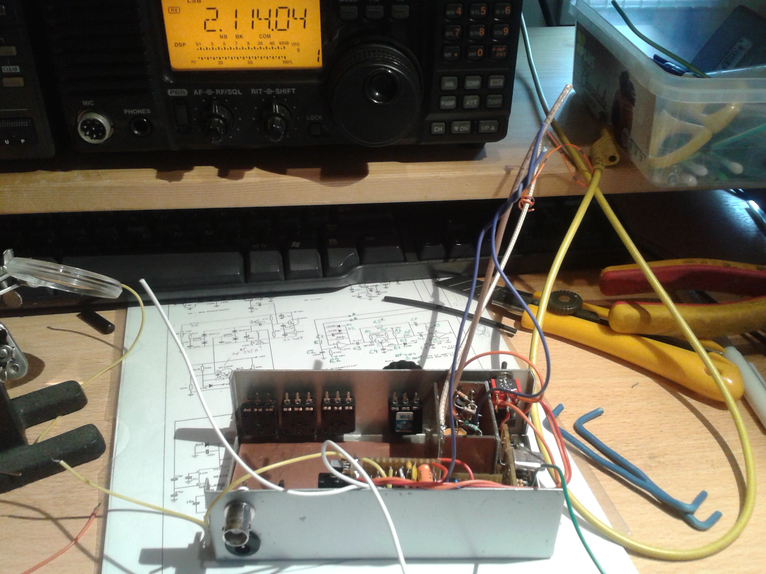
I attached a small speaker to the LF amplifier module and put my finger on the input to insert some noise; the noise came out of the speaker, so the amp seemed to work. Next I inserted a small signal at the antenna input (using the generator feature of my MiniVNA) and tuned the VFO to hear the carrier. I tuned the preselector, the carrier was really loud so I lowered the input signal and turned the coils of the preselector again to obtain the best signal.
Since the marker generator was ready too, I powered it on and turned the VFO knob, every 10kHz a small carrier was present, proving the marker generator works nicely.
The final test: I attached a couple of meters of wire to the antenna input and turned the VFO dial again. I was able to receive a couple of RTTY and CW stations, proving that the receiver really works. Since I didn’t have a proper antenna for 30m yet, I was not able to determine if the receiver is really hot, but I was very happy I actually received some stations already.
![[Image]](https://www.pa3hcm.nl/wp-content/uploads/2014/07/20140702_194859-e1404397289959.jpg)
![[Image]](https://www.pa3hcm.nl/wp-content/uploads/2014/07/20140702_194718-e1404397401969.jpg)
![[Image]](https://www.pa3hcm.nl/wp-content/uploads/2014/07/20140702_221239-e1404397247303.jpg)