5/8 Wave vertical antennas for HF
![[image]](https://www.pa3hcm.nl/wp-content/uploads/2010/10/PA230005.jpg)
Lots of radio amateurs build their own verticals. Most of them tend to stick to vertical antennas with a 1/4 or 1/2 wave sizing. Just a happy few build a 5/8 wave vertical antenna. This is remarkable, since the 5/8 has the lowest angle of radiation and a little bit more gain (depending on ground conditions). Whenever you have an open field to place an HF vertical, you should consider the 5/8 for DX’ing.
To illustrate the differences in antenna length I performed several simulations with different antenna lengths, while everything else (material, ground conditions, etc.) remained the same:
| Antenna length | Gain [dBi] | Angle of radiation [degrees] |
|---|---|---|
| 1/4 | -0.2 | 27 |
| 1/2 | 0.3 | 19 |
| 5/8 | 1.6 | 16 |
Adrian PA0RDA and I once bought a bunch of glass fibre masts with a length of 12.5 meters to do experiments with vertical antennas. After a successful experiment with a 1/4 wave vertical for 40m we wanted to build a vertical for 20m too. The fibre masts are just tall enough to hold a 5/8 vertical for 20m, the idea of building a 5/8 was born. After studying different types of verticals we concluded that the 5/8 would be the best vertical for our goal (international contesting and DX’ing).
After building a 5/8 for 20m we compared received signals with a Hy-Gain AV-12AVQ (vertical for 10/15/20m, acts as a 1/4 wave for 20m). DX signals were in most cases just a bit stronger on the 5/8. More remarkable and not less important: the noise level was noticeably lower, probably due to the fact that the 5/8 is a monoband antenna and filters out more of the RF spectrum. Remember that an antenna is also your first filter/preselector! After several years of contesting the 20m band appears one of our most successful bands, with the 5/8 wave vertical antenna being a crucial part of this success.
For 15m we have tried several types of vertical antennas, the last 2 years we used a J-pole antenna. But we were still not satisfied with this antenna and the contest results on this band, so improvement was needed by means of yet another antenna. Because of the positive results with the 5/8 for 20m we decided to build a 5/8 for 15m too.
Sizing
![[Image]](https://www.pa3hcm.nl/wp-content/uploads/2014/10/58_vert_15m_match_vector.jpg)
The vertical itself is just a simple piece of wire, placed upwards along a fibre mast. The length depends of the frequency:
wire length = 5/8 * v * c/f
Where v is the velocity factor of the wire, c the speed of light in vacuum (300.000 km/s), and f the frequency. We can simplify this to:
wire length = 187500000 * v / f
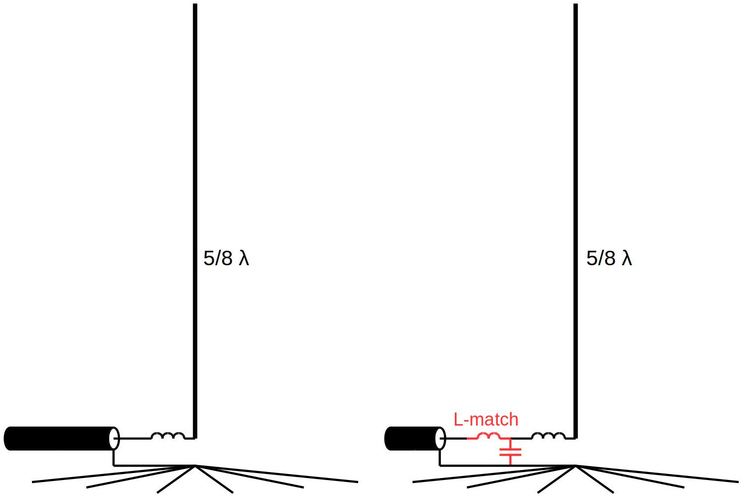
The antenna impedance (R+jX) merely depends on the ground plane, but will be rather capacitive (negative X). To feed the antenna with 50 ohm coaxial cable, a match is required to transform the antenna impedance to 50 ohms (50+j0).
We measured the impedance of our 15m antenna: 53-j328 ohm. So R=53, and X=-328. By adding an inductor with a value of +j328 the total X becomes 0 and the impedance will be 53 (+j0) ohms. This is close enough to 50 ohms, so just adding the inductor is enough to achieve a correct match.
To calculate the series inductor, we use this famous formula:
X = j * 2 * pi * f * L
We need L, so we transform this formula into:
L = X / ( j * 2 * pi * f)
Now we fill in the values, in our case X(L)=328 and f=21.2 MHz:
L = j * 328 / ( j * 2 * 3.1416 * 21.2E+6 )
L = 2.46 uH
If your R is noticeably higher than 50 ohm, you may consider to add an L-match to transform your R to about 50 ohms. Lots of calculators (online and software) are available to determine the required values, for example here or here.
Construction
The vertical itself can be made of a piece of wire along a fibre mast. If you want a more solid solution that will hold for many years, you better get some aluminium pipes and hose clamps. Anyway, we use the wire-along-the-mast. When cutting the wire, be sure to add some extra length.
The ground plane depends on your soil, in wet mud a simple ground pin will probably do the job. But in most cases you want some radials to create an artificial ground, independent of weather and ground conditions. The length of the radials is not critical, different sources advise a minimum length of 0.3 wavelength. For our 15 and 20m verticals we applied 16 radials for each antenna, each radial being about 6 meters long.
When the antenna is erected and the ground plane is in place, grab your antenna analyzer or VNA. Find the (lowest) frequency for which you have minimum return loss. For this frequency the vertical is 1/4 wavelength. To determine the frequency for which this length is 5/8 wavelength, multiply the frequency by 2.5. This is the operating frequency. Since your wire should be a bit too long, cut away some cm’s and measure again. Repeat this until the system has the correct size.
Again, grab your antenna analyzer of VNA and measure the antenna’s complex impedance (R+jX). Determine the value of the series inductor (and optionally the L and C of the L-match) as described above. The match is build into a small waterproof box, we used a box that was originally meant to put food into your freezer. A SO239 connector and 2 female 4mm connectors are placed in the lid, the components are fixed to these connectors. The coil is made using a piece of PVC pipe with a hole drilled on each end to hold the wire in place. Use a LC-meter to be sure you have the correct inductance. When including the L-match, use a ceramic high-voltage type capacitor, capable to handle the RF power.
![[Image]](https://www.pa3hcm.nl/wp-content/uploads/2014/10/20141002_165648.jpg)
These are the materials we use for our 5/8 wave vertical antennas:
- 12.5 meter fibre mast by DX-Wire, secured with PVC tape.
- Copper wire with PVC shield, normally used for electrical wiring, 1.5 mm2 (AWG #15). Here in the Netherlands it’s called “VD draad”, this wire has a velocity factor of about 0.92.
- Tie-wraps to mount the wire to the mast.
- 15mm copper pipe with 30cm wire attached, female spade connector soldered at the loose end of the wire.
- 16 radials, each made of 6 meters WD-1/TT wire (originally used by the army for field telephony), provided with female spade connectors.
- Copper pipe, bended in a circular shape, used to combine all radials. Copper wires are attached to this circle, with male spade connectors soldered at the end.
- Ropes and stakes (guys).
- Plastic box, normally used for putting food in the freezer.
- Small piece of PVC pipe to hold the inductor.
- Some more copper wire to wind the inductor.
- Optionally: high voltage capacitor, large enough to handle the power.
![[Image]](https://www.pa3hcm.nl/wp-content/uploads/2014/10/20141002_165747-e1412955332979.jpg)
Further reading
- A High-Performance 1-Wire DX Antenna, by Gary Huff K9AUB: “Give the 5/8 wave vertical a try if you want to work DX, but you just can’t afford a tower and beam. You’ll be very pleasantly surprised at its performance.”
- Book: ‘ON4UN’s Low Band DXing’, by John Devoldere ON4UN.
An earlier version of this article was also published in:
Great article and inspiration. Please ad some more detailed pictures on your site.
Great article and thank you sharing.
73’s
VE1XOP
hi
could you not shun feed a 40 ft tower in the same manor
just wondering
good artical but looking for .64 wave
thanks.
There is little difference between a 0.64 wave and a 5/8 wave, 5/8= 0.625.
I’m also looking to Build a 0.64 … but for 10M
Actually for 27.555 Mhz ..
I anybody is reading this in the future – please feel free to email and advise ..
73
Peter
Peter,
I read 21’5″ is the best overall length to use for 11meter 5/8 wavelength aluminum vertical antenna when tuned at 27.185mHz. You won’t see any difference in gain/performance with any other length to 23′.
If is posibile, plecase sentimentul to me antena schemthank you
See my reply to Raj…
Hi
Do you Build the Antenna?
How do you match the wire ?
Hi did you get it going?
Really formidable,My dear colleague ERNEST,an excellent article,Thanks
Josè Antonio Mogrovejo
HK2-DHU
From Colombia-South America
I’ve been modelling 5/8 wave verticals, 2 points you might find useful:
1/ a 5/8 wave only gives better low angle of radiation if it’s perfectly vertical. the wind-blown example in your first picture may be giving higher angles of radiation than a 1/4 wave, which has a radiation pattern that’s not so susceptible to disruption from leaning
2/ radials actually lying on the ground can resonate as a 1/2 wave (e.g have high impedace) at lengths much shorter than 1/2 wavelength, they are useless as a ground if this is happening. from the data i’ve seen, it’s best to make them quite short to steer well clear of the against ground 1/2 wave resonant frequency, about 0.15 of a wavelength seems resonably optimum for 4 or more radials (obviously the shorter length is also an advantage for portable use)
Phil, thanks for your useful input! I’ve been modelling too in the past, especially radials around 3/8 WL were a disaster, not strange since the total length (radial + vertical) makes exactly 1 WL. Apart from that, if you stay away from that 3/8 WL it’s ok, shorter or longer does not really affect the radiation. And yes, the wind does not enhance the radiation 😉
Could you add construction details and specifications for the matching inductor and capacitor?
Joe, my article explains how to calculate the series inductor for the antenna. The scope of the article does not include an explanation for how to calculate the L-match, but you can find lots of information and online calculators on the internet.
I think he may be asking what you ended up with for an inductor IE turns and diameter air, core etc..not all “get the maths”.
The 5/8th wave vertical can be an excellent DX antenna, if a user is willing to operate it over a perfect or near perfect ground radial system. This means at least 50-60 radials that are as long or longer than the antenna is tall. How do I know? Because I constructed one for 20 meters and operated it over 100 radials, each one 50′ long.
Hallo Ernest
Nice information
I have been using 28.1246 MHz for WSPR
using a 1/4 military mobile antenna, perfect match at 28MHz
the 1/4 is with its feet at about 4m a.g. behind the barn in almost free field. WSPR gave me the possibility to compare the receiving results with others in about the same area JO33hg and i found that the results are not very good at least -10dB weaker reception the 1 a 1/2 wave vertical some 30km away that antenne is also on a low pole in the field with some barns close by . Very comparable setup.
So I tried to convert my 28MHz 1/4 to a 5/8 wave
I use an aluminium tube extended with a glasfibre fishing rod with a shunted wire. the lenght of it is 6.30 meter allmost 0.64 wave for 10m
The matching i used the base of an CB antenna in the base is a matching coil air 8 windings close with a tap at 3 windings
Calulated and measured the coil is 2.8uH and about 2uH at the 5wdgs tap
The impedance of a 5/8 is (75 -425j) Ohm
https://ham.stackexchange.com/q/3783/218
so i need an coil with XL 425 to compensate that, the original base coil
happens to be the right value to compensate..
But it did not, what ever a tried i never could match this antenna to have a reasonable SWR checked cable , checked everything double triple.. used the EU1KY antenna analyser i only found a match point
at 41.5 MHz … the analyser curves i can’t make chocolate of it
I thought this would be an easy thing a 5/8 wave antenna but is isn’t
btw the radials i use are the same 2 x 2.55m wires that worked well with the 1/4
where is the bug?
Hello Jaap,
Try different radials. Your current radials are 1/4 wave, so they will be very resonant which you don’t want in this case. Stay away from 1/4 and 3/8 radials when using a 5/8 antenna. Try shorter radials, maybe just 1.5 meter. After swapping the radials, measure R+jX using your antenna analyser tuned at 28.1246 MHz. Good luck!
73, Ernest
Whos Bright Idea was it to make 5/8 radials as long as your antenna? the longest radials you need on a 5/8 antenna are 102 inch each(Times 3) Shorter radials add nothing to transmit/receive of your antenna(just a higher SWR) David
Sorry David, but I think you didn’t understand (parts of) my article. As stated the radials are to improve the conductance of the ground, therefore they should NOT be resonant and NOT be a multiple of a quarter wave together with the vertical, and a length of over 0.3 wavelength is proven to be enough to improve the groundplane. Also, the radials are laying on the ground, NOT sloping.
73, Ernest PA3HCM
i have with big attentionn read all the comments at it ssems that the different people have different results vith matching sutch long antennas but much time and mathematics and experiments can be saved if one instead of 5/8 antenna select an half wave antenna wich are truly highimpedanced lets say about 200 ohms in the end so it is a half vave antenna feed in the end and you feed it with a parralel circuit with a coil and variable condenser both in a TRANSMITTER quality wich means with more than a millimeter space in the condenser plate and the coil made of 3 mm coppar wire and this paralell circuit connects in the top to the bottom of the antenna and the bottom to the groundplanes and then the coax cableshield connects to the groundplane and the innerleader to a point some windings up from the groundplanes found experimentally but a good start are 4—–5 vindings up .—-.—-yoy has to bring the paralellcircuit in resonance before it is installed and you mark on the condenser where the point are that you have resonance the way you can put it on resonance is to place it with your tranceiver and connect one side to the radio and the other side to the antenna or a piece of wire as antenna then tune the receiver to the middle of 20 mtr then turn the condenser until the received station almost disappear and then mark the position on the condenser (the circuit must have a correct condenser // coil value so if you start with a capacity of 50 picofarad and select coilwindigs to a point you can find resonance you are on the rigth track then you install the circuit as menioned and find a coilwindintg where you get a fine match yoy can fineadjust the condenser in the circuit the but just sligthly and yoy have a antenna with a very low radiation angle and on top of that yoy can move the resonance from top to bottom of the band just by turning the condenser sligthly good luck if you are trying it works great without mathematics ,….–,.—-OZ3YT ex OX3MT.—-.—-
i wrote on my description that an half wave antenne would have a carakteristic impedance in the end of 200 ohm it was wrong it should be arround 2000 ohm
OZ3YT.—-.—-THOMAS M
Can someone give me their thoughts on a vertical 11m extended double zepp wire antenna. Any help would be greatly appreciated
Best Regards
Hello. I have a 190 ft. Tower similar to rohn 45 in my backyard that I am able to run ropes off of high enough to suspend a 5/8 wave 160m vertical. By the calculations I see here 164 feet of vertical wire with 0.3 wavelength radials would be required. I am intrigued by this and propose to get this set up before winter. Tnx for the ideas and information. WY8G,,,,Bruce.
I have read this numerous times with great interest so thank you for posting the article. I use a 1/2 wave on 20m, given this 5/8th wave needs to be ground mounted (so radials are flat) and has 16 rather long radials of 6m each… is it likely to be worth the significant effort ? (making it, deploying it and packing it down again)
Will it produce 1.2dB gain at a lower angle compared to a 1/2 wave with a 5m above earth feed point ? I ask as you mentioned it was only slightly better than a well made 1/4 wave. I do like to make antennas but mainly ones that perform better than the one I currently use. At this time I cannot see if these 5/8th wave ground mounted antennas will lower angle and add 1.2dB gain.. over a 1/2 wave at 5m feed point.(The current centre if the 1/2 wave would be approx 2.5m higher (10m) than the 5/8 wave which I believe would be at 7.5m)
In short, will this ground mounted 5/8 wave outperform a 1/2 wave with a feed point of 5m off the ground ?
I am up for experimenting but if the answer is a no from the outset then it may be time wasted. Many thanks for your thoughts in advance.
Thanks for you reply! Ground radials are completely different from elevated radials. Ground radials improve ground conductivity, their length is not critical but you better stay away from lengths which makes them a multiple of 1/4 wavelengths (vertical included). Elevated radials are usually resonant (combined with the vertical). I haven’t used elevated radials combined with 5/8 wave verticals, so I can’t tell you if it makes a difference. Elevated radials result in a taller construction, but you’ll just need 3-4 radials. The 5/8 has a lower radiation angle, so requires more spacing around to be effective. That said, it’s one of the best verticals I’ve ever experienced, it easily outperforms 1/4 wave verticals. I haven’t done 1/2 wave verticals yet, since the 5/8 is not much taller and shows better figures, at least in the books. I highly recommend ON4UN’s book ‘Low Band DXing’, it gives a very well explanation on these subjects.
Thanks for the reply. I have only 2 options:
5/8 wave ground mounted (ground mounted radials) fed 10cms above earth.
and 1/2 wave with feed at 5m
I have actually made a 5/8th wave now so time will tell, I just don’t know whether the 5/8 ground mounted with radials will perform as well or better than a 1/2 wave fed @ 5m.
Can the 5/8 produce gain and lower take off despite being on the ground ? (As the 1/2 wave has the elevated feed point advantage and I wonder if that means the 1/2 wave will work as good or maybe even better than the 5/8 wave) It is very difficult to judge these things for DX as we know conditions change all the time and patterns of performance tend only to show themselves after many, many portable outings.
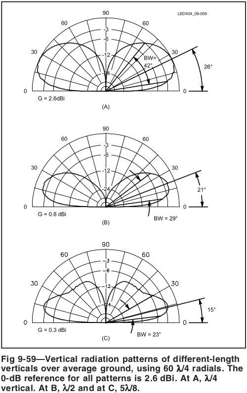
Stated that the lower endpoint of both antenna’s is close above the ground, the 5/8 will surely have a lower radiation angle than the 1/2 wave. The picture down here shows the theoretical difference between 1/4, 1/2 and 5/8. I took this image from the book ‘Low Band DXing’, 4th edition (2005), by John Devoldere ON4UN. IMHO it is a must-read on the subject of HF verticals (no, I don’t get royalties).
Remember that the radiation angle is heavily influenced by the ground. Ground radials improve the ground’s electrical conductivity and makes your antenna less dependent of the soil. That’s why they are (should) not resonant. I sometimes use a mix of different lengths for my verticals. You don’t have to bury them, just ensure they are close to the ground (to gain capacitive coupling). I use tent pegs to keep them in place…
Many thanks for taking the time putting that diagram up, appreciated. The book is very difficult to get hold of, sadly…. and very expensive when it does appear. Nonetheless I will keep my eyes open for it. The 5/8 wave made a 6,000 miles contact in weak conditions using 100W on its first test. So it does work, there is no doubt here. It is surprising to see the minuscule difference between a 1/2 wave and a 5/8 wave in those diagrams. Between 8 and 15 degrees the 1/2 wave appears to have more gain than the 5/8 wave. And below 8 degrees the difference is extremely small.
I suspect the 1/2 wave mounted a little higher (which is easier to do as you don’t necessarily require an extensive ground mounted radial system) the 5/8 wave will be virtually identical as the increased distance from the ground brings the 1/2 waves lower lobe down.
This can matter when portable as set up and take down time needs to be factored in. I use both (1/2 wave EFHW mono band cut for 20m with 50 small radials which technically may or may not be necessary… I put them there just as a bit of counterpoise to soak up any CMC) and a DIY 5/8 wave so over time I will try and work out of one performs better than the other. That is going to take quite a long time if it is even possible at all, I do not think the difference between a 1/2 wave and a 5/8 will be the difference between a contact or not.
It will be fun to use both and try and find out, which is a great part of the hobby… thanks for your inspiring article. All the best and 73. I shall report back in a few years if there appears winner.
https://g5epc.blogspot.com/2021/04/g5epc-portable-amateur-radio-station-qrz.html
Wow, I just throw up a vertical, 3 ft off the ground on a T post, and get an almost perfect match and get contacts over 8000 miles away. did it for 10m, 12m, 17m. And NO GROUND RADIALS on either antenna.
Most interested in this but i need a pointer
how did you determin this number 53-j328 ohm measurement details please
thanks and currently building a 20m 5/8
As the text states, we measured it! 🙂
There is lots of gear available to measure complex impedance, like antennas. Search for “antenna analyzer” and you will find lots of them.