Automatic antenna tuner using an Arduino
Introduction
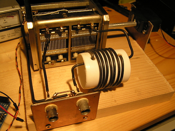
The Arduino board is a fantastic tool for rapid prototyping, and can help radio amateurs in lots of homebrew projects. I wanted to demonstrate that it is very easy to build an automatic antenna tuner with the Arduino. I connected an old SWR meter to one of my Arduino boards. Furthermore I build a simple L-tuner with a fixed coil and a rotating capacitor (400pF). The capacitor is driven by a servo, also connected to the Arduino. By doing a full sweep with the capacitor, the Arduino tries to find the position with the lowest SWR. After the sweep it turns the capacitor to that position. You can view the video below to see the tuner in action. Mind the SWR meter (right needle) in the back while the capacitor is rotating.
![[Image]](https://www.pa3hcm.nl/wp-content/uploads/2011/11/20141215_193205.jpg)
Version 2
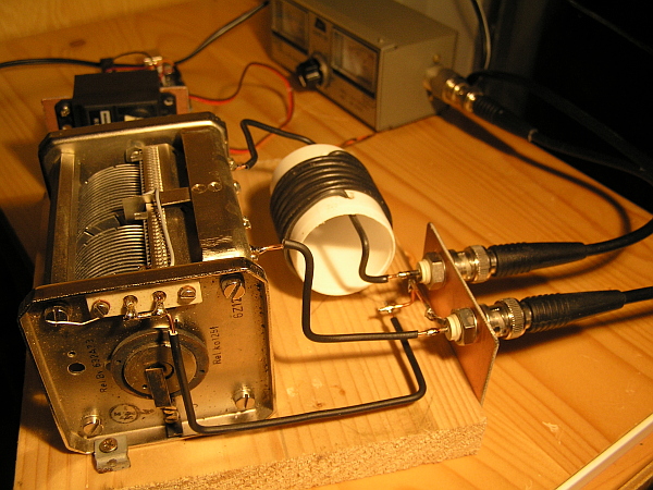
I was so surprised by the simplicity, that I decided to extend the tuner. The next step is to vary the inductor. Therefore I made a new one with an extra connection in the middle. The inductor is now 8cm long, 4cm diameter, and has 14 windings with a tap halfway. I added a relay to switch between the half or the full inductance. Now the software is modified, it does two sweeps with the capacitor, one with half induction, and another one with full induction. Again, it searches for the best combination. I tested it, and now it finds a nice SWR for almost any load! The movie shows a slow version, to allow you to see it working. The code below is the fast version, it tunes within 2 seconds!
This is the circuit diagram:
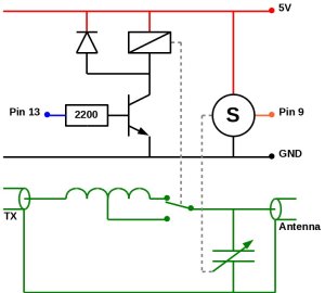
The green part is the RF section, which is electrically isolated from the control section. The control section is connected to the Arduino board, pins are given. The SWR meter is not in the circuit, but should be placed between the tuner and the transmitter (TX). The DC output of the SWR-meter is connected to analog input 0 of the Arduino. Parts are not critical. The transistor can be any regular NPN type, e.g. BC547. The resistor is 2200 ohm in the circuit, but could also be 4k7 of 1k or anything between. The diode handles the backfire current of the relay, and could be of almost any type, e.g. 1N4148. The servo is a generic 180 degrees 5 volt servo and mechanically attached to the capacitor. The inductor is switched by a 5 volt relay, which must be capable to handle the desired RF power.
Before using this code, remember it is still for demo purposes, so there is no code in there for a “tune” button or so. It simply tunes, wait 10 seconds, tunes again, waits 10 seconds, tunes again, etc… For building a real tuner, you will also have to compare the reflected power to the forward power. So you will have to read both meters, compare them, and depending on the results you probably want to alarm the user when no low SWR could be found.
// AutoTuner v2.01
// by PA3HCM

#include <Servo.h>   // We will use a servo
Servo cap;           // for rotating the capacitor
int capPin = 9;      // attached to pin 9
int indPin = 13;     // Inductor relay on pin 13
int reflPin = 0;     // Reflection input on analog pin 0
int pos = 0;

boolean bestIndPos = HIGH;
int capPos = 0;
int bestCapPos = 0;
int refl = 0;
int bestRefl = 1023;

void setup() {
  pinMode(capPin, OUTPUT);
  pinMode(indPin, OUTPUT);
  cap.attach(capPin);
}

void loop() {
  // reset
  bestCapPos = 0;
  bestIndPos = HIGH;
  bestRefl = 1023;

  cap.write(0);      // turn capacitor to start position
  delay(500);        // this will take a bit of time, so wait

  // find best reflection with full inductance
  digitalWrite(indPin, HIGH);
  delay(200);
  for(pos = 0; pos < 180; pos += 3)
  {
    cap.write(pos);
    delay(15);
    refl = analogRead(reflPin);
    if (refl < bestRefl) {
      bestRefl = refl;
      bestCapPos = pos;
      bestIndPos = HIGH;
    }
  }

  // find best reflection with reduced inductance
  digitalWrite(indPin, LOW);
  delay(200);
  for(pos = 180; pos > 0; pos -= 3)
  {
    cap.write(pos);
    delay(15);
    refl = analogRead(reflPin);
    if (refl < bestRefl) {
      bestRefl = refl;
      bestCapPos = pos;
      bestIndPos = LOW;
    }
  }

  // select best capacitance and inductance
  digitalWrite(indPin, bestIndPos);
  cap.write(bestCapPos);

  // wait before re-entering the loop...
  delay(10000);
}
Have you tried using the Arduino in an RF environment? I thought about using an Arduino to tune my Omega match using stepper motors to turn vacuum variable caps, but was concerned about RF interaction with the Arduino.
I used my Icom IC-730 in AM mode to provide RF, with a maximum output 40 watts. I tested the tuner on different shortwave bands, mainly 40 and 80 meters, and never experienced any RF issues with the Arduino. Note that I directly inserted the SWR signal into the Arduino for these experiments, in a final design I would suggest some kind of signal scaling and filtering. To be honest, I was also a bit surprised that no RFI problems didn’t occur…
I do know they need a bit of shielding. I built my antenna rotator with an arduino, and when I run 1kw on 10 meters, or 1kw 6 meters, my display show a screen full of random symbols, and the controlls stop working. I would have to shut off the rotator and restart it to get it working again. I put a couple of snap on chokes on my control cable running up to the rotator, and it works great now.
Jake
kd7veaj
You need 1000 Watts? Just wondering why. You can probably guess that I’m a QRP guy and make loads of contacts on less than a handful of Watts.
1KW of RF would stop most microprocessor things stone dead in the water, but proper design is the key to making it possible. Not really very difficult.
I like the simplicity of this design. To solve the “when to tune issue”, could you setup the tune button as the Arduino reset. Then move the code out of the loop block and into the setup block. Basically every time the program runs it finds a solution. When you need a new solution you restart the Arduinio.
nice tuner. could you clarify more on how you pulled your swr signal from your meter. I’m having a mental block on that one have you tapped the fwd/rev leads from the sensor to the meter or does your meter have an output of some sort? is there a blocking diode in there or any other circuit or is it just output from the meter to the analog inputs on the meter? or are you using another swore bridge integrated in the Arduino.
thanks 73
Brian, you’re not the first who asks this question. I just added a picture to the article showing the wiring of my SWR meter.
[…] https://www.pa3hcm.nl/?p=336 […]
Very nice description – I especially liked that – for the demo – you kept the tuner simple. So the working principle is really easiy to understand and the Video gives a real good Illustration.
Vy 73 de Stefan HB9TWS
What did use for the servo motor?
I used the Modelcraft RS-2 servo for this experiment, which was a cheap 5 volt servo. This model is obsolete now, but a nice replacement would be the Modelcraft BMS-410C. Please mention that the capacitor I used in this tuner runs very easy, so it does not require much torque to get around.
Hello, and thanks for the nice sketch.
I have modified it just a little bit and added a “push to tune” function and a servo cut-off relay. I find them very sensitive to rf.
Seems to be working ok on my remotely semi-auto tuned link coupled tuner, which feeds a double extended zepp. A nice feature would be to use a stepper motor, and a vaccum variable capacitor.. Here is the sketch // Tommy, SA2CLC
// AutoTuner v2.01
// by PA3HCM
#include // We will use a servo
Servo cap; // for rotating the capacitor
int capPin = 9; // attached to pin 9
int indPin = 12; // Inductor relay on pin 13
int reflPin = 1; // Reflection input on analog pin 0
int forwPin =2;
int pos = 0;
int reflvalue = analogRead(A1);
int buttonInput = 4;
int ServoRelay = 6;
int buttonState = 0;
boolean bestIndPos = HIGH;
int capPos = 0;
int bestCapPos = 0;
int refl = 0;
int bestRefl = 1023;
int forw =0;
int bestforw = 0;
void setup() {
pinMode(capPin, OUTPUT);
pinMode(indPin, OUTPUT);
cap.attach(capPin);
pinMode(ServoRelay, OUTPUT);
pinMode(buttonInput, INPUT);
digitalWrite(buttonInput, HIGH);
}
void loop() {
buttonState = digitalRead(buttonInput);
if (buttonState == HIGH) {
digitalWrite(ServoRelay, LOW);
}
else {
digitalWrite(ServoRelay, HIGH);
delay (10);
bestCapPos = 0;
bestIndPos = HIGH;
bestRefl = 1023;
bestforw = 0;
cap.write(0); // turn capacitor to start position
delay(200); // this will take a bit of time, so wait
// find best reflection with full inductance
digitalWrite(indPin, HIGH);
delay(200);
for(pos = 0; pos bestforw)
refl = analogRead(reflPin);
if (refl 0; pos -= 2)
{
cap.write(pos);
delay(15);
forw = analogRead(forwPin);
if (forw > bestforw)
refl = analogRead(reflPin);
if (refl < bestRefl) {
bestRefl = refl;
bestCapPos = pos;
bestIndPos = LOW;
}
}
delay (300);
// select best capacitance and inductance
digitalWrite(indPin, bestIndPos);
cap.write(bestCapPos);
}
}
The following code out of Tommy’s modification does not compile.
// find best reflection with full inductance
digitalWrite(indPin, HIGH);
delay(200);
for(pos = 0; pos bestforw)
refl = analogRead(reflPin);
if (refl 0; pos -= 2)
{
cap.write(pos);
delay(15);
forw = analogRead(forwPin);
if (forw > bestforw)
refl = analogRead(reflPin);
if (refl < bestRefl) {
bestRefl = refl;
bestCapPos = pos;
bestIndPos = LOW;
}
See lines containing for(…)
and
if (…)
Tommy’s modification isvery bad.
int indPin = 12; // Inductor relay on pin 13
int reflPin = 1; // Reflection input on analog pin 0
int reflvalue = analogRead(A1);
for(pos = 0; pos bestforw)
etc.
Ernest
Is er al een definitieve tuner door jou gebouwd die goed werkt.
Of blijft het bij dit proto type??
ik hoor graag.Mart
Hey Mart, sorry to tell but I don’t have any further plans to design and build a serious ATU.
73, Ernest PA3HCM
Hallo,
Ik zag je commentaar over die automatische antenne tuner va PA3HCM
Ben jij nog wat verder gekomen met dat ontwerp.
Ik zie wel dat er in die arduino sketch nogal wat fouten zitten
Ik wou dit maken met een rolspoel en een condensator.
Ik heb de hardware klaar nu de arduino aansturing nog
Graag hoor ik van je
Evert
Geen updates, de code zal ondertussen wel verouderd zijn inderdaad. Het was slechts een ideetje, een concept, een experiment… 😉
Hi, thank you for posting this, I am doing something very similar. Currently my code does include a SWR calculation which for now is only outputted over the serial port. I am also using PWM to drive a servo. My thoughts at the moment are to select inductor based on the band data from the rig and only motorise the capacitors. thought provoking indeed.
Hi, a very impressive concept model, I have used an Arduino with a display in an RF power meter but I want to progress to an Arduino driven T-match tuner. You have certainly given me some ideas. 73
Hi, I tried to simulate this project in Proteus ISIS using a arduino and a servo and I used a potentiometer with 5V to simulate the SWR voltage to A0 of the arduino , but it does not work. The servo just keeps sweeping; it never stops, even when I lower the voltage to 0V. What could be the problem ?
Hi Robert! I’m not familiar with Proteus ISIS, but I know simulations can be quite tricky. I have done simulations in the past with Spice variants and with Microcap and I know how hard it can be to do a successful simulation. Now, In this case the impedance should change while the servo loops, that’s the whole trick of a tuner. You also have to attach a load, probably some 50 ohms resistor with an LC network that resonates somewhere within the frequency range of your tuner and transmitter. Ah, transmitter.. yeah you need that as well. So lots to think about for a nice simulation. I hope this will help you out a bit… Email me screenshots, values, circuit, etc if you want further assistance, without that information I’m afraid I can’t help you any further for now.
73, Ernest PA3HCM