Pixie2 QRP transceiver for 80m
Introduction
The smallest QRP transceiver for 80 meters, called “Pixie 2”, is a very nice project to start building your own equipment. Minimum components, maximum fun. The spec’s are poor, but what else might you expect for just a few dollars?
The G QRP Club compiled a nice booklet called The Pixie File, which includes the history of this little transceiver and some variants.
Circuit description
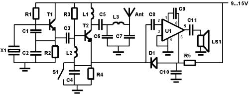
The crystal oscillator is a simple parallel-mode Colpitts type (actually it’s a Clapp oscillator), designed for 3.5 MHz. The frequency depends on the used crystal, the preferred value is of course 3.56 MHz, the worldwide QRP-frequency! The “PA” is made with a 2N2219, delivering max. 400 mW to the antenna. But, this transistor is also a mixer for receiving signals.
The LM386 is a populair AF amplifier, and gives enough gain to hear the stronger stations.
I’m currently building this ‘toy’ for myself. So I don’t have any experience with it yet, but Jan PA3AGP was very enthousiastic about his results with this tiny transceiver. He made QSO’s from France with dutch amateurs during his holiday, which was a distance of over 600 km. But even much greater distances must be possible. A good antenna will give much better results.
Of course it’s possible to do lots of modifications and improvements to this transceiver, but for most people it’s just the fun to keep it as simple as possible. Just add the TX/RX shift modification to make operating somewhat easier and to increase the chance on a QSO. If you want to do more mod’s, don’t do that, but start a new project to build a more serious transceiver and leave your Pixie 2 this way.
Some hints
- Build the transceiver on a piece of PCB, using the “high-wire” method. All components which are connected to ground are soldered at the PCB, other nodes are floating. Don’t use a “normal” box, but use its small size to build it in a funny, original or non-expecting thing. It will increase the fun and will result in more oh’s and ah’s of your spectators. I saw amateurs who built the transceiver in a box which was originally for sweets. Other amateurs built it in an old morse key, so that it seems that he was just screwing a wire on the key and was able to make QSO’s…
- You can add 2 capacitors, and a switch to connect one capacitor at a time to the ground plane. Take one capacitor of 33pF, and one of 1nF. Switching from one to the other capacitor will result in a frequency shift of the oscillator, necessary if you want to operate normally, without hoping that the opposite station doesn’t have a small difference in transmitting and receiving…
- Use NP0 capacitors for C1 and C2, and optionally for the extra C’s of the previous hint. This will provide a more stable oscillator.
Circuit
Components
R1 47k
R2 1,5k
R3 33k
R4 10k
R5 1k
C1 100pF
C2 100pF
C3 82pF
C4 47nF
C5 10nF
C6 820pF
C7 820pF
C8 100nF
C9 10uF
C10 10uF
C11 10uF
L1 15…22uH
L2 100uH
L3 2,2uH
D1 1N4148
T1 2N2222
T2 2N2219
U1 LM386N-1
X1 Crystal 3.56MHz
LS1 Speaker 8 ohm 0,3W or headphones
SW1 Morse key
![[image]](https://www.pa3hcm.nl/wp-content/uploads/2013/12/enh-logo1.jpg)

Can you post me a good antenna link for the amazing transceiver?
There are lots of options. You may try a G5RV or a Zepp, these are rather easy to construct.
Thanks for an interesting web page.
Why not use the LM387 pin 7 method for muting as proposed by LA3ZA? It gets round the horrid 1k ohm ‘volts starving’ in the original circuit and allows the amp to operate more linearly and is much less likely to oscillate.
A Zobel network on the output will also greatly increase stability.
In addition, the LM386 data sheet shows a really easy way to give some fairly severe treble cut to prevent the output having such a very wide and unnecessary audio bandwidth. (The published 10k/33n might need a tweak for our CW use. I used 10n/1k8)
Something slightly more complex is replacing the LPF with a BPF. I used one published by Hans Summers. Although a BPF is not generally recommended for use with a transmitter, it greatly reduces any broadcast breakthrough from below the operating band of the crude receiver of the QRP Pixie.
The Pixie will never compare to a K3, or even an old HW-8, but a few very simple mods will make it actually usable.
73,
Ian
(Second line should read: “Why not use the LM386 pin 7 method…” Sorry.)
If you like to use it on the air you should put a 40pf disk capacitor and a switch in series with the xtal. The switch is in parallel with the capacitor. This is done for Rx and Tx offset.
Two anti parallel diodes connected to the headphone plug will cure the nasty clicks in the headphone. 2N4001.