30m QRP transceiver – Part 1
![[Image]](https://www.pa3hcm.nl/wp-content/uploads/2014/03/qrm30m-lf-modules.jpg)
This summer I want to go walking in the beautiful highlands of Scotland, together with my wife. The mobile phone coverage in this desolate area is none or poor, but hey… I’m a radio amateur! For a daily “sign of life” I need a lightweight transceiver, and 30m (10.100 – 10.150 MHz) seems to be a perfect band for this purpose.
After browsing the web for designs, I stumbled on the website of Onno PA2OHH. Besides lots of other interesting QRP projects, I found his NiceRig 40-30 QRP Transceiver. I immediately fell in love with this design and decided to build this thing.
Building this rig takes quite some time, so I publish this project in different posts, showing you the progress of this project.
Block diagram
![[Image]](https://www.pa3hcm.nl/wp-content/uploads/2014/03/pa2ohh-qrp30blbig.gif)
Circuit
![[Image]](https://www.pa3hcm.nl/wp-content/uploads/2014/03/pa2ohh-qrp302abig.gif)
![[Image]](https://www.pa3hcm.nl/wp-content/uploads/2014/03/pa2ohh-qrp302bbig.gif)
General construction
I split the circuit into separate units. I use breadboard for the LF units and copper clad for RF. The RF circuits are directly soldered onto the copper clad (“dead bug” method).
Audio amplifier
This is the most easy part of the transmitter. I built it on breadboard, including 2 ground pins to solder thid module on the copper clad. The circuit is very traditional, using the popular LM386 amplifier chip. Onno suggests an audio level switch due to limited space at the front panel, but I replaced it with a potmeter since I expect it will fit.
![[Image]](https://www.pa3hcm.nl/wp-content/uploads/2014/03/qrp30m-audioamp-1.jpg)
![[Image]](https://www.pa3hcm.nl/wp-content/uploads/2014/03/qrp30m-audioamp-2.jpg)
![[Image]](https://www.pa3hcm.nl/wp-content/uploads/2014/03/qrp30m-audioamp-3.jpg)
Marker generator
The marker generator creates a square wave of 10kHz, resulting in a carrier at 10kHz with harmonics at 20kHz, 30kHz, 40kHz, etc. When in receive mode, carriers will also occur in the 30m band, at 10.100, 10.110, 10.120, etc. Since the trx has no counter/display, these markers are very useful to set the VFO dial. The generator can be activated with a switch at the front panel.
I built the generator on breadboard. The variable capacitor allows you to callibrate the oscillator.
![[Image]](https://www.pa3hcm.nl/wp-content/uploads/2014/03/qrp30m-markergen-1.jpg)
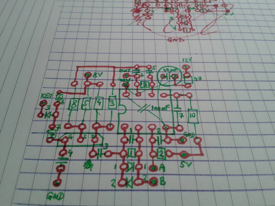
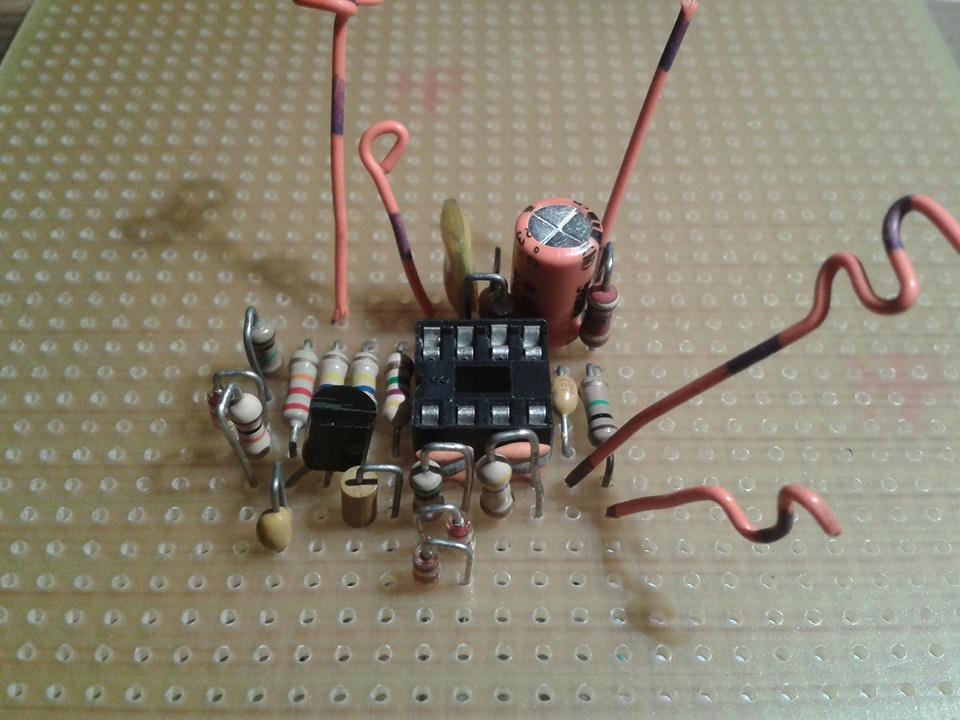
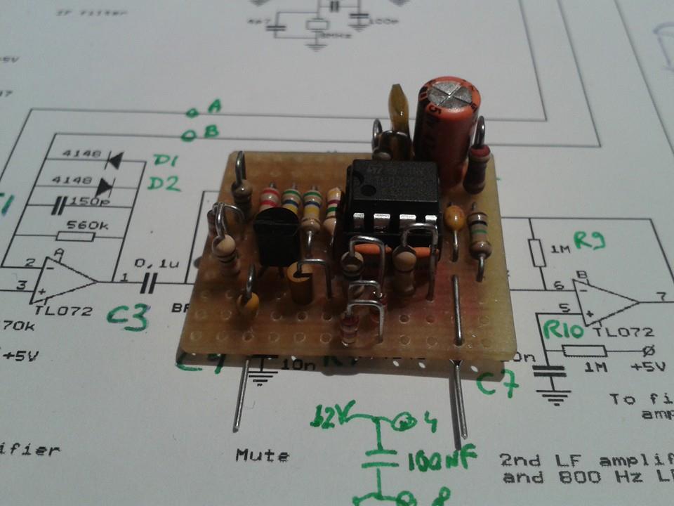
Audio preamp and filter
This module handles the audio demodulated by the second mixer in the receiver part. It also mutes audio when you hit the morse key, and narrows the audio bandwidth for a more comforable CW reception.
The module is built around a TL072 dual opamp. The first opamp is used to amplify the output signal of the second NE612 mixer. The signal is limited by 2 diodes. The output passes the BF256 transistor, which mutes the audio when key down. The nice thing is that a very small amount of your transmitted signal is still inserted in the receiver, so you can monitor your own signal and no sidetone generator is needed. The second opamp circuit is an audio bandpass filter.
Dit is nog een zelfbouw met een hoofdletter Z.
Als je die TRX af hebt maak ik graag een 2-way cw qrp qso met je Ernest. Ik zal binnenkort mijn 30m qrp trx weer eens opzoeken.
Heb je ook plannen voor SOTA activatie in Schotland?
When finished, I’m looking forward for a sched, Mark. I might do some SOTA in GM, not sure about that yet.
Just had 2 nice cw qso’s om 30 meters. It it one of my favorite bands. Not too busy, good condx during the day and most of the time you will find stations on 30M who are in for a chat.
Lieber Ernest,
grosses Intresse für deinen 30m QRP Transceiver. Will ihn nachbauen. Nur eine Frage: Ist der VFO ohne Abschirmung stabil genug? Finde ich toll, dass Amateure immer wieder solche kleinen Geräte selbst bauen. Grosse Begeisterung.
Georg, DK4HG
Hello Georg, Nice to hear that you’re planning to build this little TRX too!
The VFO is covered in copper clad, except from the top. This appeared to be very stable already, so no top lid was needed. The second article regarding this TRX shows all details regarding the VFO, see https://www.pa3hcm.nl/?p=636.