Fox transmitter for 80m
Introduction
Fox hunting is one of the many aspects of ham radio. It’s some kind of game, where the “fox” is a little transmitter, and competitors have to locate it using a directional antenna and receiver. I already built a special receiver for fox hunting, and my wife (PD2W) built one too. So having 2 receivers it would be a nice idea to add a fox to these, to get a complete mini-fox-hunt-kit. One of the members at the club pointed me at the so-called “OXO transmitter”. I looked it up at the internet, and immediately liked its simplicity. So I started to build it.
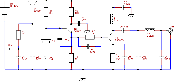
Schematic
How it works
Transistor T2 with surrounding components is a simple collpits crystal oscillator. The oscillating frequency mainly depends on the value of the crystal X1, but can be varied some kHz by tuning C3.
The oscillator signal is transfered to T3, which has to be a transistor which can handle some more power. I used a 2N3866, but you may use almost any power transistor you like. L1 and C7 block RF feedback to your DC, just pick a big inductor for this application. I used a 15mH inductor, simply because I found it in my junkbox.
The OXO transmitter has a simple keying circuit which powers the amplifier (T3) on and off, so the oscillator runs continiously. Since my fox is in a plastic box, you can still hear the oscillator with your receiver, so I decided to key the oscillator aswell. The result is that the power of the whole transmitter is keyed now, using T1/R1/C1/C2. The advantage is that almost no power is consumed when not keying the transmitter, which saves your battery.
With key-down the transmitter will put a whole spectrum of frequencies in the air. If you have a oscilloscope, just look at the signal at the collector of T3: this is definitely not a clean sinus wave! So I added a PI-filter (L2/C10/C11) to shape the signal. The output power will be about 500 mW.
Building tips
You may create a PCB layout for this, but I decided to build it “high-wire”. Take some unetched PCB board, and start with a component that has to be connected to ground. From that point solder the rest of the components. It is a simple and fast way of building prototype RF circuits.
You probably have to create L2 yourself. I’m still not really good in creating coils, but for this one don’t use those inductors you can buy in the local electronics shop that are shaped like a resistor! It fully saturizes, no signal will get through.
T3 and R6 will get warm, so put a cooling star on T3 and use a resistor for 6 which is capable to handle more power.
Shopping list
R1 1k
R2 33k
R3 100
R4 1k
R5 1k
R6 39

C1 100n
C2 100n
C3 60p trimmer
C4 100p
C5 100n
C6 100p
C7 100n
C8 10n
C9 100n
C10 560p
C11 560p

L1 15mH
L2 2.2uH

X1 3.579MHz

T1 BD136
T2 BC107
T3 2N3866

B1 9..12V battery
CW-keyer
This is just the transmitter, you will probably also need a CW keyer. I built a simple one using a PIC processor, which can be found here.
Warning
In most countries you have to be a licensed radio amateur to build and/or use this transmitter.
Excellent work . 73 de vu3inj, indrajit from India. Hope to copy this fox and catch it.
HI,
I have the project to build your qrp transmitter but I need to know how many turns you maid for L2.
And if I can use a 2N4427 for the final.
Many thanks
Marc F6FEC
Hello Marc,
The 2N3866 and 2N4427 are quite exchangeable, so I don’t expect issues with that.
To calculate the correct inductance, I always use this website to find out the number of turns: http://toroids.info/
73, Ernest PA3HCM
Hi from Greece..nice project!
I want to ask in this circuit if the 100nf capacitor value is correct between collector and ground of T2 transistor?..I say that because in other similar circuits this capacitor value is 100 to 220pf.
Hi Elias,
It’s definitely correct, it’s purpose is to removes any RF ripple/feedback from the DC power at the collector input.
73, Ernest PA3HCM