Short DL6WU yagi for 23cm
![[Image]](https://www.pa3hcm.nl/wp-content/uploads/2014/12/20141231_135147.jpg)
In the previous Winter I built a HB9CV-in-a-box for 23cm for my uplink to the local ATV repeater PI6ATV. Although this antenna works nicely, its gain just isn’t enough when their 23cm preamp is broken (which, unfortunately, is the case most of the time). To achieve a more steady uplink, I decided to build an antenna with a bit more gain, at least 6 dB extra compared to the HB9CV. A short yagi should make this possible.
Design criteria
There are lots of designs available for yagi antennas. Guenter Hoch DL6WU has researched this subject for decades, nowadays his design formulae are accepted throughout the world in both commercial and home made antennas. Many other designs are actually just small modifications of the DL6WU formulae. In the past I built a couple of 2m beams using DL6WU’s design, so I decided to use this again, now for my 23cm yagi. I started with my design criteria:
- Center frequency: 1260 MHz
- Bandwidth (3 dB): 1240-1280 MHz
- Gain: 10 dBd or more
- Polarization: horizontal
- Mount: in front of mast
- Lightweight
Construction
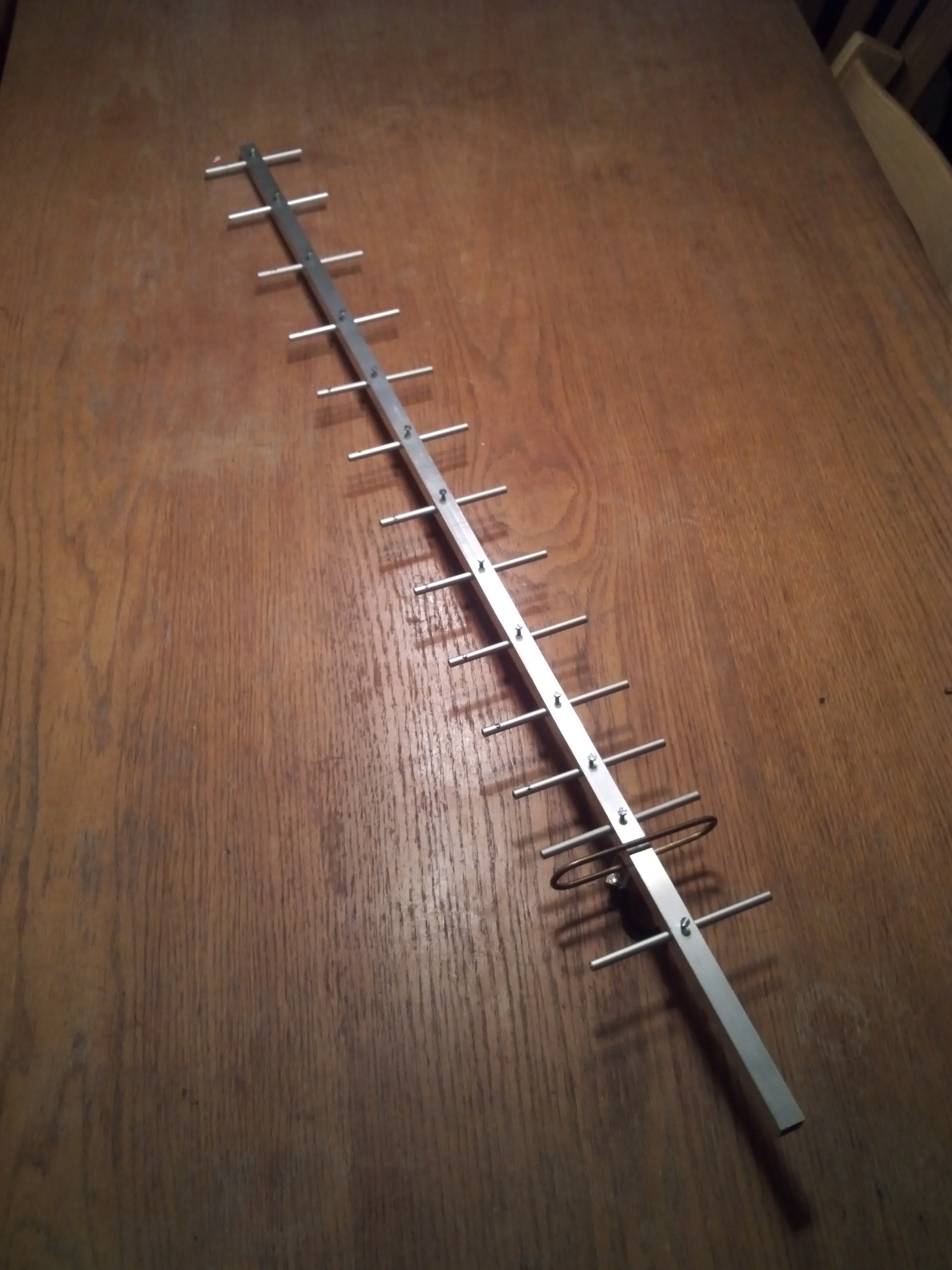
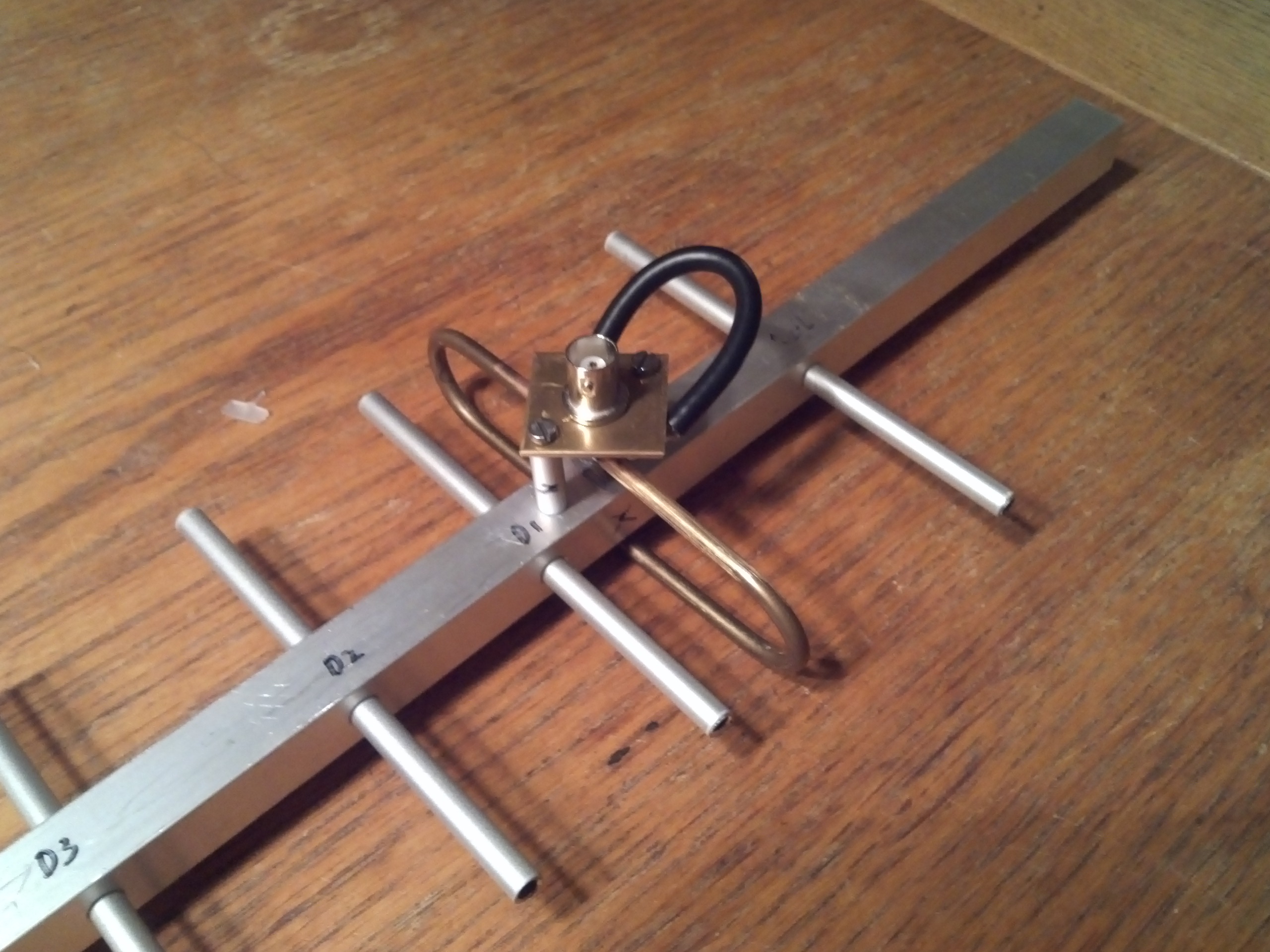
Because of low weight and easy handling I mostly use aluminium to construct VHF/UHF antennas. This material is also easy to drill, saw and grind. You can buy it in most DIY shops. For this antenna I bought an square bar (15x15mm), made of aluminium, length 1 meter. At one end I mounted a standard available mast mount, leaving about 90cm for the actual antenna. Using the DL6WU formulae, this results in a 14 element yagi, with a gain of over 13 dBd. I used the DL6WU spreadsheet calculator of DF2CK to calculate all measurements. Unfortunately DF2CK’s website has vanished. Luckely I kept a local copy of the sheet to calculate your own yagi, click here to download the sheet. I used AlMg3 welding rods for the radials. These rods have a diameter of 4 mm. The dipole is made of 6 mm2 copper wire, matched with a matching loop (1/2 wavelength coax or semi-rigid) and mounted to a female N connector.
These are my inputs for the spreadsheet:
- Frequency MHz: 1260
- Boom diameter cm.: 1.5
- Element diameter mm.: 4
- Element Thru Boom (“Y/N”): Y
- Boom Length (Metres): 0.89
This spreadsheet returned these specifications, the real specifications will differ a bit, but it will give you an idea what to expect:
- Gain: 13.6 dBd
- Usable bandwidth: 1234.8 to 1285.2 MHz
And it returned these element sizes:
| Element | Length | Distance to reflector |
|---|---|---|
| Reflector | 11.61 | – |
| Driver | 11.29 | 5.71 |
| Dir 1 | 10.83 | 7.50 |
| Dir 2 | 10.69 | 11.78 |
| Dir 3 | 10.56 | 16.89 |
| Dir 4 | 10.44 | 22.84 |
| Dir 5 | 10.33 | 29.50 |
| Dir 6 | 10.23 | 36.64 |
| Dir 7 | 10.13 | 44.14 |
| Dir 8 | 10.04 | 51.99 |
| Dir 9 | 9.96 | 60.20 |
| Dir 10 | 9.88 | 68.76 |
| Dir 11 | 9.81 | 77.69 |
| Dir 12 | 9.75 | 86.85 |
![[Image]](https://www.pa3hcm.nl/wp-content/uploads/2014/12/20140323_110711-e1420034453965.jpg)
![[Image]](https://www.pa3hcm.nl/wp-content/uploads/2014/12/20140323_111047-e1420034395383.jpg)
![[Image]](https://www.pa3hcm.nl/wp-content/uploads/2014/12/20140323_113248-e1420034406923.jpg)
![[Image]](https://www.pa3hcm.nl/wp-content/uploads/2014/12/20140323_113356-e1420034416324.jpg)
![[Image]](https://www.pa3hcm.nl/wp-content/uploads/2014/12/20140323_114254-e1420034439665.jpg)
![[Image]](https://www.pa3hcm.nl/wp-content/uploads/2014/12/20140323_123545.jpg)
![[Image]](https://www.pa3hcm.nl/wp-content/uploads/2014/12/20140323_153839.jpg)
![[Image]](https://www.pa3hcm.nl/wp-content/uploads/2014/12/20140326_193931.jpg)
![[Image]](https://www.pa3hcm.nl/wp-content/uploads/2014/12/20140326_195036.jpg)
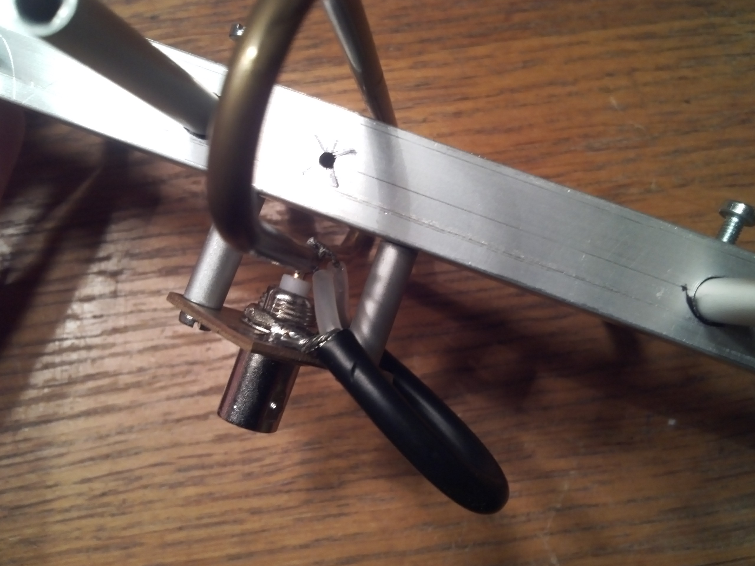
The finished antenna looks very good, but I have to admit that the driver is a bit wacky. Any hints to improve this are welcome.
Results
The ATV repeater now receives a decent signal, resulting in a steady and colourful picture. Unfortunately I don’t have equipment to measure the impedance and resonance point of my antenna. Whenever I’m able to measure this, I will update this article.
![[Image]](https://www.pa3hcm.nl/wp-content/uploads/2014/12/20141231_135234.jpg)
Reproductions
Lex PH2LB managed to reproduce this antenna to examine whether it’s possible to make contacts at the 23cm band from his home. He send me some pictures:
If you’ve built your version of this antenna, please let me know your experiences, and send me some pictures of it!
This article was also published in:
Pleas can I have the design for 23 cm antenna
15 element will be nice
I used this spreadsheet for calculating the design: http://df2ck.de/tech/23cm_yagi/DL6WU.XLS
[…] Short DL6WU yagi for 23cm (www.pa) […]
Where can i find the dimensions of the Dipole???
The driver is the dipole, the given length is the outside diameter. The height is not critical, about 3 cm.
When calculating a similar antenna, is it possible to apply a reflector, a vibrator and directors from an aluminum rod with a diameter of 6…8 mm? The center frequency for the calculation is 1420 MHz and the antenna must be narrowband and should be as narrow as possible. The antenna traverse I think is made of a square tube 20x20x2 instead of 15×15.
Unfortunately the website of DF2CK has vanished, but I kept a local copy of the sheet. It’s included in the article now. For the “traverse” I prefer using 15x15mm square tube, to lower the influence of the boom on the elements.
Ernest
i been looking at the 23cm beams be made. some people use 15mm ,20 mm and 25mm.
15mm is just under 5/8 inch. i think i found a piece of 15mm x 25mm aluminum tubing. what do you think of using that for a boom, which for me is 1/2 inch x 1 inch. do you think that would influence the beam ? i see the calculator doesn’t do rectangle. would like a input from you on this.
K0KDO Kevin
I think 15x25mm is ok, orentation should be upwards, so only 15mm of each element is ‘covered’ by the beam. For calculations you can use 15x15mm, that will be fine.
John VK5DJ has a Yagi Calculator as a program on his website that I’ve used to make three beams. They’re all DL6WU type designs and it’s very clear to use with practical results and dimensions
tnx voor het excelblad, ik ben inmiddels begonnen om een antenne voor 13 cm te maken. Uitgaande van een standaard profiel vierkant aluminium buis 15x15x1000. voor de stralers gebruik ik rvs 2mm. Het wordt een antenne met 22 elementen (incl. straler en reflector) die ook voor de mast gemonteerd gaat worden.